The simplest thing is to pick a preset matching the label on the packaging
(M100, M120, SP110…) in the Spring → preset
field. The presets are calibrated to the nominal energy: M100 ≈ 1.00 J,
M120 ≈ 1.44 J, SP110 ≈ 1.51 J and so on.
The simulator supports linear and progressive springs. Linear ones (marked
M) have all their coils evenly spaced, whereas on progressive ones
(marked SP) the coils are unevenly spaced.
If you’re sure your spring doesn’t match the presets (it’s more likely that the
replica you measured it in isn’t optimally set up) – you can adjust the
Stiffness parameter until the simulation output gives
you the energy you want.
Measuring the spring guide bearing
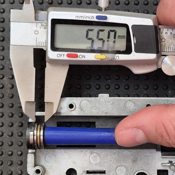
Measure the thickness of the ball bearing (or metal / plastic spacer) on the
spring guide with calipers, in millimetres, measured from the plane in the
gearbox from which its length is also measured (to the front edge of the
cylinder). Enter that thickness into
Spring → spring guide bearing.
For guides without a bearing you normally enter 0 – but watch how the guide
seats: some sit a bit forward of that plane even without a bearing, so you have
to include that offset in the value.
For those who count coils on the spring
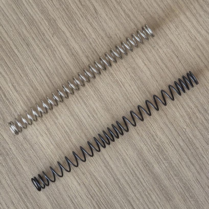
Top linear, bottom progressive spring. Both 1.8 J.
What the spring markings mean: the M mark is for linear
springs. On those, compressing the spring by two inches takes twice the
force needed to compress it by just one inch. The force grows linearly
with compression – hence the name.
The SP mark denotes progressive springs. On those the force
doesn’t grow linearly with compression, but increases progressively. That
makes it easier for the motor to get going and reduces wear on the mechanism
over time. The main advantage of progressive over linear springs is that,
thanks to their uneven coils, they damp firing vibrations faster and therefore
ring less.
The number on M springs tells you the speed (in m/s) a 0.20 g BB
would reach in a properly dimensioned replica: M120 means 120 m/s. Non-linear
SP springs tie the same number to a 0.25 g BB – which automatically
means 25 % more energy than an M spring with the same number.
Incidentally, 25 % more energy means only 11.8 % more speed, because energy
grows with the square of speed and in linear proportion to mass.
Don’t blindly trust the number
One manufacturer’s springs can differ quite a bit from another’s springs with
the same marking. The problem is that the measurement method isn’t precisely
defined. Yes, it measures the BB’s energy at the muzzle – but there’s no
convention for how the replica should be set up or which BB mass to use.
The Lab presets hit the nominal value on an ideally set-up replica, so if your
chronograph disagrees with the simulation – before you doubt the model, doubt
the spring’s declared rating, or the accuracy of the data you fed the simulator.
Cheaper chronographs can also show all sorts of things.
I’ve noticed that since around 2023 quality control has slipped at many – even
brand-name – makers, with two “identical” springs varying quite a bit in power.
So it’s best to keep your own reference replica in which you chronograph a
spring’s actual power.
Advanced: custom spring
For non-standard springs you can bypass the preset and enter everything
manually:
stiffness k (N/mm) – how many newtons it takes to
compress the spring by 1 mm. You can measure it with a weight of known mass:
put the weight on the spring and watch how far it compresses – but be sure to
start from the fully relaxed position. E.g. a 1 kg weight (≈ 9.8 N)
compressing the spring by 10 mm means k ≈ 0.98 N/mm.
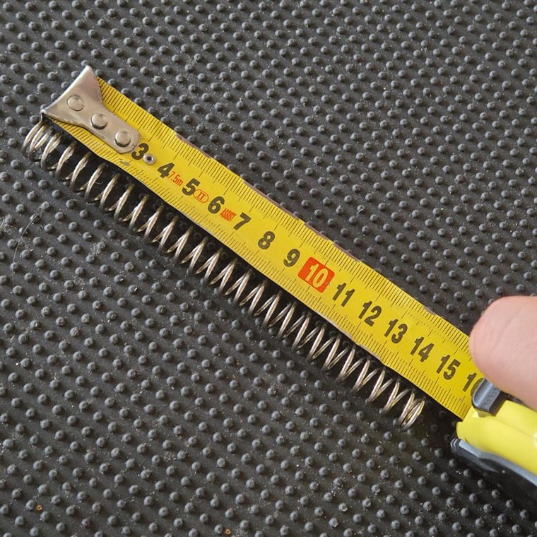
free length – tape measure, spring unloaded
spring mass – a scale reading to 0.1 g will do
Modelling a non-linear spring
For non-linear springs, besides stiffness, free length and mass, you also have
to enter the wire thickness Wire ⌀. You add coil
groups by clicking the Add group button and then
entering the coil count (need not be a whole number)
and the pitch in the group. There are usually two
alternating density groups. The terminator – the compressed and partly ground-down
coil at each end of the spring – isn’t counted.
For an example, look at how the SP springs are modelled in the presets.
Bearings
On the spring guide, and/or in the piston, usually sit bearings – most often an
axial (thrust) one with its ball race, or metal / nylon spacers.
If the spring is too strong, you can dial its power down by removing one of
those bearings – or just a part of one, e.g. the ball race – which reduces the
thickness. But careful: if you pull a bearing out of the piston, the complete
piston with its head must be re-weighed and the new mass entered into
piston + head mass.
The thicknesses go into spring guide bearing (with
the spring) and piston head bearing (in the piston
settings block).
Cutting the spring
Another way to bring energy down: cut off a coil or two, which lowers the
spring’s preload. The catch is that a shortened spring becomes stiffer per
millimetre (fewer active coils doing the same job), but the drop in preload
dominates.
The process is fairly counterintuitive, so if you shorten it “by eye” you’ll
very likely get it wrong. That’s why a spring is usually cut a little at a time,
checking on the chronograph.
The simulator can make this much easier: under Advanced there’s a
spring cutoff setting – enter how many millimetres
you’d cut off and it works out the resulting output power for you.
Tip: a stronger spring is not a free win. The simulations show that
efficiency drops with power – a weaker spring converts over 60 % of its work
into BB energy, while the strongest ones fall below 50 %. More violent
compression means more heat and more losses. So: the weakest spring that
reaches your target energy is also the most efficient one – don’t
“over-spring and compensate”.
We use Google Analytics to understand site traffic. Analytics cookies are set only if you agree. Privacy Policy